A retaining wall in the Meridian-Kessler neighborhood faces a completely different set of demands than one built near the White River floodplain in Broad Ripple. The historic north-side neighborhoods often sit on dense, overconsolidated glacial till that stands up well during excavation, while the alluvial deposits closer to the river corridor bring groundwater, silts, and soft clays into the equation. Indianapolis sits squarely in Climate Zone 5, where the frost depth reaches 36 inches per the IBC, so every retaining wall design we develop must account for frost heave and seasonal moisture swings. The city's geology—dominated by the Wisconsin-age till plain—gives us a solid bearing stratum, but the variability across Marion County means we never assume uniformity from one site to the next. A proper retaining wall design ties site-specific geotechnical data into the structural analysis, and in zones with marginal backfill we often coordinate with a stone columns program to improve the retained soil mass before wall construction begins.
Indianapolis glacial till is a reliable bearing material, but unmanaged groundwater turns a sound retaining wall design into a maintenance headache within two freeze-thaw seasons.
Methodology and scope
Local considerations
We inspected a 14-foot block wall behind a commercial building off 96th Street that had rotated outward nearly four inches at the top. The original retaining wall design had no continuous drain at the base, and the backfill was compacted silty clay straight from the site excavation. Over two winters, water built up behind the stem, froze, and the lateral pressure cycled well beyond what the wall could resist. The repair required complete demolition of the upper courses, installation of a geocomposite drain against the back of the wall, and a granular chimney connected to daylight drainage. That single project cost the owner more than triple what a properly designed drainage system would have added during original construction. Indianapolis sees roughly 42 inches of rain per year, concentrated in spring and early summer, so hydrostatic buildup behind a wall is not a rare event—it is an annual certainty. Overlooking internal drainage or specifying on-site clay as backfill are the two most expensive shortcuts we see in local retaining wall failures.
Applicable standards
ASCE 7-22 – Minimum Design Loads and Associated Criteria for Buildings and Other Structures, IBC 2021 Chapter 18 – Soils and Foundations, Table 1806.2 Presumptive Load-Bearing Values, INDOT Standard Specifications Section 207 – Earth Retaining Structures
Associated technical services
Gravity and Segmental Block Wall Design
For walls up to 6–8 feet on residential and light commercial sites. We check bearing on the glacial till, specify the leveling pad embedment for freeze protection, and detail the drainage system so the wall drains freely year-round.
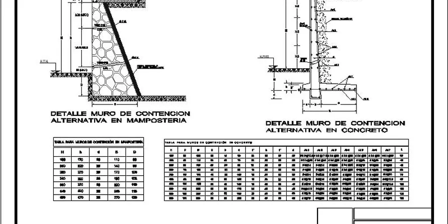
Reinforced Concrete Cantilever Wall Engineering
Applied to basement retention, loading docks, and grade separations. Our analysis covers stem bending, heel and toe shear, and global stability. We size reinforcing per ACI 318 and confirm the factor of safety against overturning exceeds 1.5 under saturated backfill conditions.
Mechanically Stabilized Earth Wall Design
Used along INDOT corridors and commercial developments where wall heights exceed 12 feet. We evaluate the interaction between the select granular fill and the reinforcement strips or geogrids, and we design the facing connection for the 75-year service life required by INDOT.
Forensic Evaluation and Repair Design
When an existing wall shows cracking, tilting, or drainage staining, we perform a condition assessment, review the original retaining wall design, and develop a repair scheme that addresses the root cause—usually poor drainage or underestimated lateral loads.
Typical parameters
Frequently asked questions
What is the typical cost range for a retaining wall design in Indianapolis?
Professional retaining wall design fees for a residential or light commercial wall in the Indianapolis area typically range from US$1,200 to US$4,170, depending on the wall height, complexity, and whether a geotechnical investigation is included. Taller walls, MSE structures, or walls requiring a registered structural engineer seal fall toward the upper end of that range.
How deep should a retaining wall footing be in Marion County?
The bottom of the footing must extend below the 36-inch frost line specified by the IBC for Climate Zone 5. For most retaining wall designs in Indianapolis, we specify a minimum embedment of 42 to 48 inches below the finished grade at the toe, and we increase that depth when the wall retains saturated ground or when the till is weathered near the surface.
Do I need a building permit for a retaining wall in Indianapolis?
The City of Indianapolis Department of Business and Neighborhood Services generally requires a permit for retaining walls over 4 feet in height measured from the bottom of the footing to the top of the wall. Walls supporting a surcharge, such as a driveway or building, require a permit and a stamped retaining wall design regardless of height.
What type of backfill is recommended behind a retaining wall in central Indiana?
We specify free-draining granular material, typically INDOT No. 53 crushed stone or AASHTO No. 57 stone, placed in lifts and compacted to at least 95 percent of standard Proctor density. On-site clay or silty soils should never be used as backfill because they trap water and dramatically increase lateral pressure on the wall.
How do you handle groundwater when designing a retaining wall near the White River?
Sites near the White River or its tributaries often have a shallow water table and permeable alluvial soils. In those conditions, our retaining wall design includes an underdrain system at the base, a continuous granular drainage chimney behind the wall, and sometimes a geocomposite drain on the back of the stem. We also run seepage analyses to confirm the wall is stable under the maximum anticipated hydrostatic condition.